
First time I saw a trimpot (trim-pot as trimmer potentiometer, 10KΩ in my case) I immediaty started wondering why the heck does it have 3 pins. Would 2 not be just enough? I started googling and, surprisingly, the answer was not that easy to find. I'll share what I found out, but first, let me answer the title question: how to use a trimpot?
-
First of all, if you flip the trimpot over, you will see 3 pins, just as on the diagram I clumsily prepared:

That is the back of your trimpot. Well, you get the idea. - Let's describe what's on the diagram. The two horizontally aligned pins (let's call them A and B) are your reference points and the third pin is called wiper.
-
Now, the idea behind the trimpot is *brutally* simple:
- Resistance between A and B is always constant (in my case, 10KΩ)
- Restistance A-wiper and B-wiper varies depending on the trimpot's knob (or screw, whatever you have) so that if A-wiper is 10% of trimpot's nominal value, B-wiper will be (100% - 10%) of trimpot's nominal value.

To follow up, let me list a couple of interesting facts about trimpots. Great majority of them has 3 pins, but there actually are trimpots with just two pins, like this one:

Why 3 and not 2 then? From what I've read, two most popular reasons are:
- To keep soldered trimpots in place while adjusting their values. A lot of people simply ignore either pin A or B.
- To utilise the fact that when the resistance on one side increases (e.g. A-wiper), the other one decreases (e.g. B-wiper), and vice-versa.
To illustrate how trimpots exactly work, I ran a couple of simple measurements (top: wiper, left: A, right: B). Before I start, though, please keep in mind that neighter my multimeter nor the trimpot are perfect, so expect some measurement imperfections. Also, the multimeter measures resistance in KΩ.
| Trimpot's knob goes all the way down the B-wiper side. Whole resistance is allocated between A and wiper. | |

|

|
| A-wiper measurement | B-wiper measurement |
|
|
|
| Trimpot's knob goes all the way down the A-wiper side. Whole resistance is allocated between B and wiper. | |

|

|
| A-wiper measurement | B-wiper measurement |
|
|
|
| Trimpot's knob is somewhere in the middle of the range. Whole resistance is shared equally between A-wiper and B-wiper. | |

|

|
| A-wiper measurement. I expected something around 5KΩ, but 5.00KΩ exactly is pure concidence. | B-wiper measurement. 5.07KΩ - that's more like it! |
|
|
|
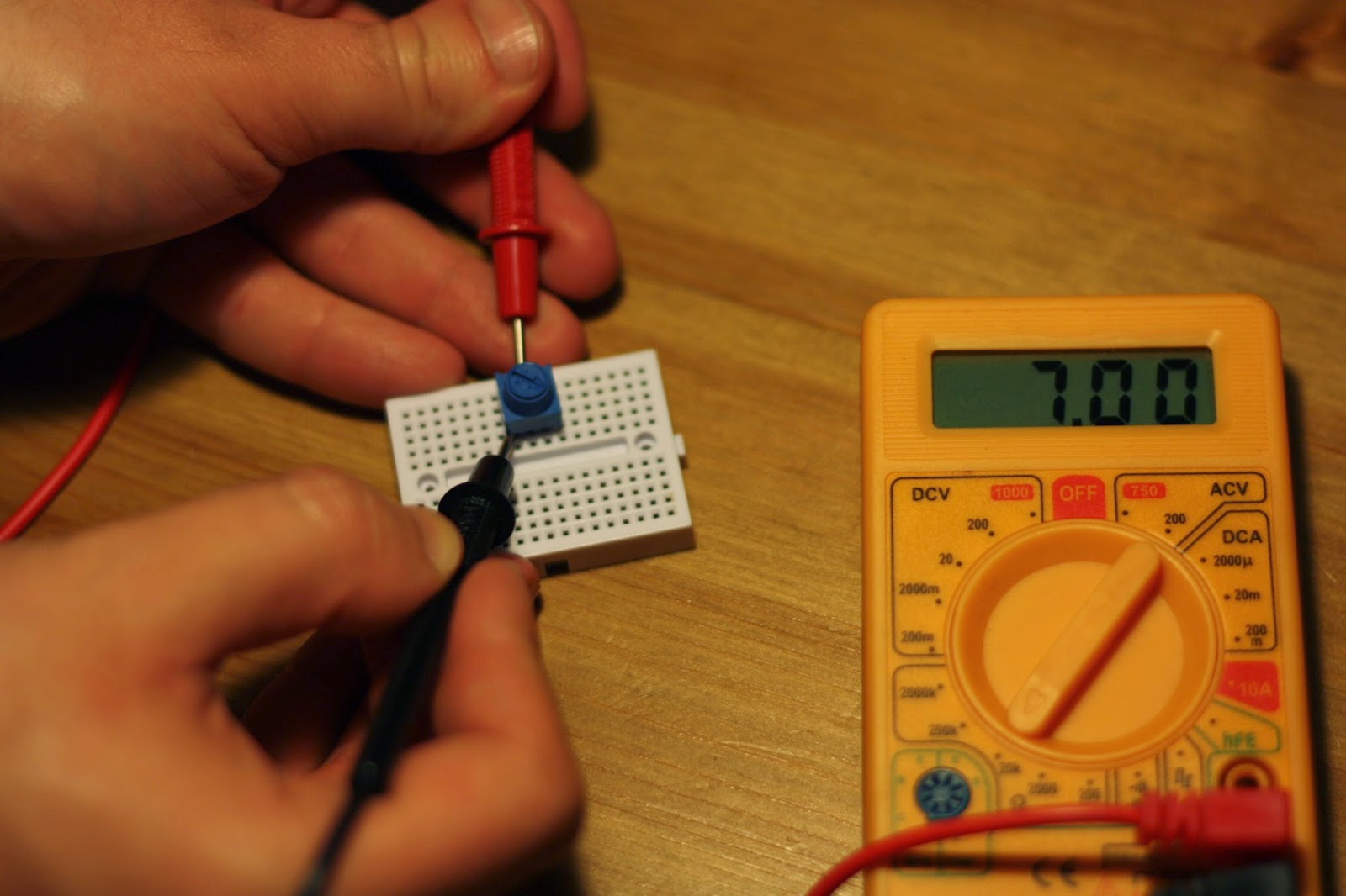
| Trimpot's knob is somewhere on the B-wiper side which means this side's resistance will be lower compared to the A-wiper side. Additionally, 7.00KΩ + 3.06KΩ = ~10KΩ, which is the nominal value of the trimpot. | |
|

|
| A-wiper measurement. | B-wiper measurement. |
|
|
|
| And finally, even though the trimpot's knob goes all the way down the B-wiper side, A-B resistance is always constant. | |

|
|
| A-B measurement. | |

No comments:
Post a Comment